- Description
- Technical Specifications
- Support Documents
Overview
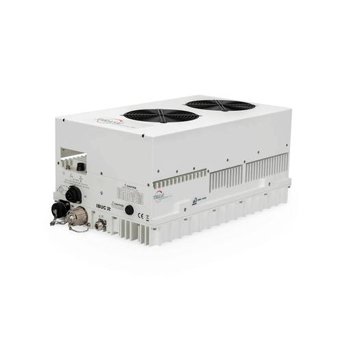
The IBUC R has all of the advanced IBUC features and the upgraded RJ45 M&C connector.
IBUC offers significant benefits:
- Low terminal cost
- Simple design and installation
- Superior RF performance
- Simplified 1+1 configuration
New interfaces connect you to extensive M&C facilities for network management or local access. This powerful new M&C enables:
- Trouble-free commissioning with easy, point-and-click installation/configuration
- Continuous verification of performance with time-stamped alarm history
- Simplified monitoring of terminal status
IBUC Advantages
Integrated BUC/SSPA for higher performance and reliability. Upgraded with a weatherized RJ45 M&C interface connector for simplified cable installation. All models available with integral AC power supply or separate DC power supply.
Internal 10MHz reference option automatically switches to internal reference when external reference is not detected. Low phase noise better than IESS308/309 requirements by a minimum of 5 dB. NMS-friendly interfaces enable remote management of your earth station RF.
Embedded Web pages provide management for small networks using any Web browser. AGC or ALC circuits hold gain or output level constant. 30 dB User-adjustable gain in 0.1 dB steps preserves modem dynamic range.
Advanced user interfaces
- TCP/IP HTTP with embedded Web pages
- SNMP
- TELNET through TCP/IP
- FSK through TX IFL cable
- RS232/485 serial port
- Hand-held terminal
Frequency range | |
---|---|
Band 1 Std Ku RF IF |
14.00 to 14.50 GHz 950 to 1450 MHz |
Band 2 Full Ku RF IF |
13.75 to 14.50 GHz 950 to 1700 MHz |
Band 3 Low Ku RF IF |
12.75 to 13.25 GHz 950 to 1450 MHz |
Input | |
VSWR / Impedance | 1.5:1 max / 50 Ohm |
Input Connector | Type N female (50 Ohm) |
Input Connector options | Type F (75 Ohm), TNC (50 Ohm) |
Input power detector | -55 to –20 dBm |
Gain | |
Small Signal Gain (L-band to RF) with attenuator set to 0 dB | |
50 W | 78 dB min |
60 W | 79 dB min |
80 W | 80 dB min |
100 W | 81 dB min |
Attenuator range | 30 dB variable in 0.1 dB steps |
RF Output | |
Interface | WR75 cover with groove |
VSWR | 1.5:1 max |
IMD3 (2 carriers, 3 dB TOBO) | -24 dBc max |
Level stability with ALC | ±0.5 dB |
Output power detector range | Rated power to –20 dB |
Power reading accuracy | ±1.0 dB max. |
Harmonics | -50 dBc max. |
Output Noise Power Density | |
TX < -75 dBm/Hz RX < -145 dBm/Hz |
|
SSB Phase Noise | |
10 Hz | -115 dBc/Hz -50 dBc/Hz |
100 Hz | -140 dBc/Hz -75 dBc/Hz |
1 kHz | -150 dBc/Hz -85 dBc/Hz |
10 kHz | -155 dBc/Hz -90 dBc/Hz |
100 kHz | n/a -95 dBc/Hz |
1 MHz | n/a -110 dBc/Hz |
External Reference (multiplexed on TX I FL) | |
Frequency | 10 MHz |
Level | -12 to +5 dBm |
Internal Reference - optional | |
Local Oscillator Frequency | |
Sense / Non-Inverting | |
Band 1 | 13050 MHz |
Band 2 | 12800 MHz |
Band 3 | 11800 MHz |
Monitor and Control | |
Ethernet (HTTP , Telnet, SNMP ), via RJ45 connector, | |
RS232/485, Hand-held Terminal via MS-type connector, | |
FSK multiplexed on TX I FL. | |
Environmental | |
Operating temperature | -40oC to +55oC |
Relative humidity | 100% condensing |
Altitude | 10,000 ft., (3,000 m) ASL |
(View our PDF Datasheet for more information) |