


SATCOM Services - Global Satellite Equipment Distributor & Integrator
SATCOM Simplified.
SATCOM Services offers a widge range of new satellite and wireless communications products worldwide. Our satellite communication service has provided VSAT Satellite Hardware and space segment solutions to a broad base of enterprise and government customers. We have built new teleports, GSM networks and private networks for our expanding customer base. Contact our team of experts to develop a solution that exactly fits your needs.
Learn More
Featured Products
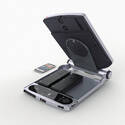

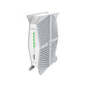
Satcube Ku Band Briefcase Terminal
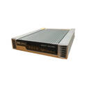

Newtec MDM3315 Satellite Modem
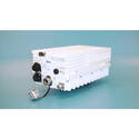

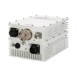
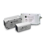
Terrasat IBUC 2 C-Band 5W-60W BUCs
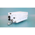
Terrasat IBUC 2 Ku-band 4W-40W

iDirect X7 Satellite Router enterprise class solution
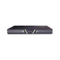
iDirect iQ Desktop+ Satellite Modem
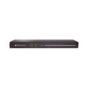
iDirect iQ 200 Rackmount Satellite Modem
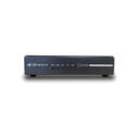
iDirect iQ Desktop Satellite Modem
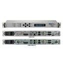

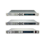
Comtech CDM-570A/L & CDM-570A/L-IP Satellite Modems
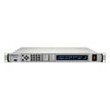
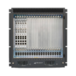
Comtech SLM-5650B Satellite Modem


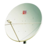
CPI 3.8M Tx/Rx VSAT Antenna Series 1385


AvL 1.2m Vehicle-Mount / DriveAway Mobile VSAT
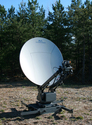
AvL Model 1.2m 1080FA FlyAway Mobile VSAT Antenna

Cross Up/Downconverter 70MHz 950-1525MHz (L-Band)
About SATCOM Services
SATCOM-Services has 30 years’ experience in satellite communication networks. We are a long standing Satellite Equipment Master Distributor and have an expansive knowledge of our large selection of satellite products.
Global Networks and Systems
With a network of C, Ka and Ku-band earth stations, we support private and corporate solutions for data, voice and video services via customer-dedicated networks.
Products
A complete range of equipment and services for satellite communications systems projects are available from the top manufacturers including: iDirect, Comtech EF Data, Terrasat, Norsat, AVL, UHP, BAIRD, AVCOM, C-COM, NJRC, Sat-Lite, SATCUBE, Skyware Global, CPI Satcom, Xicom, Teledyne/Paradise Datacom, Cross Technologies and more.
Our International Satellite Network Service
We offer the enterprise user high functionality and turn-key implementation, providing reliable, cost-efficient data network functionality and robust broadband access.
We are also a full service integrator where we build, operate and transfer full communications networks to our clients. We offer the following services and solutions: